Generating Cyclic Redundancy Checks (CRC) in Controller Area Network (CAN) Bus Frames
For anyone who's dealt with in-vehicle networks, the term 'CAN bus' is probably a familiar one. Controller Area Network (CAN) bus is a communication protocol that has become a standard in automotives and industrial automation for effective, resilient data transmission. The efficiency and reliability of this system rely on various error detection mechanisms, and one of the most critical ones is the Cyclic Redundancy Check, commonly known as CRC. This blog post will explore how CRC is generated in a CAN bus frame.
A Brief Overview of CAN bus
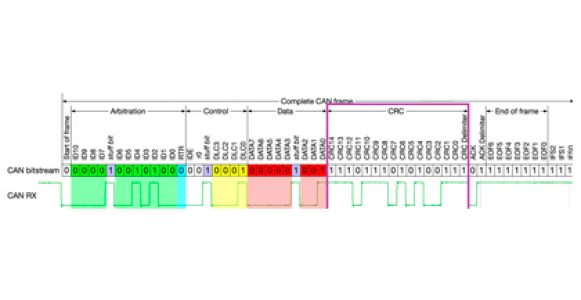
The CAN protocol was designed to facilitate communication between different parts of a vehicle without the need for a host computer. The primary constituents of a CAN system are nodes (microcontrollers) that send and receive messages. These messages are transmitted in units called frames, each of which contains different fields, including a start of frame, arbitration, control, data, CRC, acknowledgment, end of frame, and an interframe space.
What is CRC?
CRC is a powerful technique for error checking in digital systems and is used extensively in various communication protocols, including CAN. It involves appending a certain set of bits to the message data, calculated based on the polynomial division of the data bits. The receiver also performs the same calculation, and if the CRCs match, the data is deemed to be correct.
CRC in CAN bus Frame
In a CAN bus frame, the CRC field follows the data field. It contains 15 bits for the CRC itself and one bit (CRC delimiter) that is always recessive (logic '1'). The CRC is calculated based on the preceding parts of the frame: SOF (Start of Frame), Arbitration Field, Control Field, Data Field.
The CRC-15 polynomial used in standard CAN is X^15 + X^14 + X^10 + X^8 + X^7 + X^4 + X^3 + 1. For CAN FD (flexible data-rate), a more robust CRC-17 or CRC-21 is used for larger payloads.
Generating the CRC
Here's a simplified step-by-step process for generating a CRC for a CAN frame:
Initialization: Initialize a 15-bit shift register with all bits set to 1. For CAN FD, initialize a 17 or 21 bit register, depending on the payload size.
Polynomial Division: Perform a bitwise exclusive OR (XOR) operation on the shift register with the input frame bits, beginning from the SOF bit and extending through the Data Field. After each XOR operation, shift the register to the left by one bit, bringing in the next bit of the frame.
Calculation: When a '1' is shifted out of the register (MSB side), XOR the register's content with the pre-set CRC polynomial (CRC-15 for standard CAN or CRC-17/CRC-21 for CAN FD).
Result: The final content of the shift register after processing all the frame's bits is the generated CRC.
Conclusion
The use of the CRC in the CAN bus system underscores the protocol's inherent design for high integrity and fault tolerance. CRC helps ensure that the data your systems send is the same data that your devices receive, making it a vital part of any robust digital communication system.
Learning to manually generate the CRC can be an interesting educational exercise. However, keep in mind that in practical applications, this process is typically handled by the CAN controller hardware or by libraries in software.
This brief exploration into the generation of CRC in a CAN bus frame offers a window into the fascinating world of digital communications and error detection methodologies. It showcases the intricate and elegant measures taken to ensure data integrity, contributing to the reliable, efficient, and safe operation of modern vehicles and industrial systems.
